🔀 CML Lab Rebuild, Part 3: VLANs, OSPF & a Resilient Routed Core
Welcome back! 👋 In Part 2, I ripped up my original plans, pivoted to a modern routed campus design, and planned out our dual-stack /16 and /48 addressing scheme. This time, the lab finally stops being just a drawing and starts behaving like an actual network! 🚀
VLAN services are going live on the access switch, our routed links are getting their point-to-point IP addresses, and OSPF is officially stepping in to handle the heavy lifting of finding the best path.
The goal for this stage was simple: build each layer in a way that I can prove. Rather than just stopping at a green topology diagram and hoping for the best, I wanted hard evidence at every step: gateway checks, neighbour adjacencies, routing-table verifications, and end-to-end dual-stack pings. 🕵️♂️
| Build stage | What changed | Proof point |
|---|---|---|
| Access services | Site 1 VLANs and dual-stack SVIs on HQ-ASW-01 | IPv4 and IPv6 gateway status |
| Routed core | Point-to-point IPv4 /31 and IPv6 /127 links, plus loopbacks | Transit reachability from the access and distribution layers |
| Dynamic routing | OSPF for IPv4 and IPv6 | Neighbours, ECMP routes, and a resilient path to HQ-EDGE-01 |
🏢 HQ Access Services: Bringing VLANs to Life
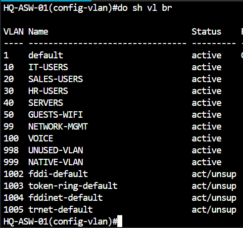
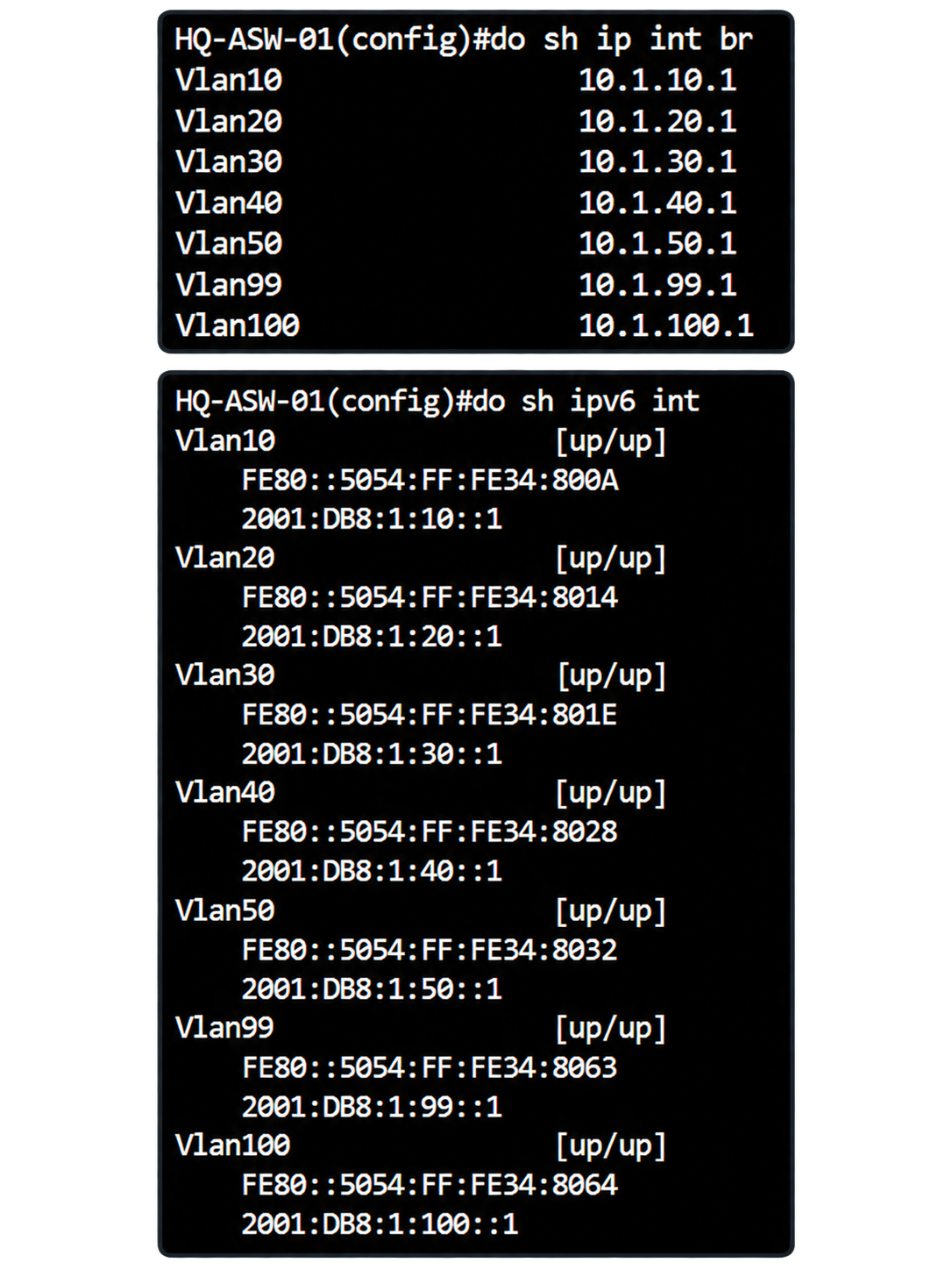
I started right at the edge on HQ-ASW-01. This is where those Site 1 VLANs we planned in Part 2 graduate from being just rows in a spreadsheet to actual, useful services.
Each Switch Virtual Interface (SVI) gives its VLAN a shiny new IPv4 and IPv6 default gateway. I was careful to keep the naming and addressing conventions we hashed out in the previous post. This is the moment the routed-access design starts to feel real. Eventually, end-user devices will use these SVIs as their first hop, but for now, the switch itself can use these dual-stack gateways to cleanly participate in the wider infrastructure.
🔗 The Routed Core: Small Prefixes, Zero Waste
Next up: the infrastructure links. Remember how deep we went into the subnetting weeds in Part 2? 🌿 That discipline continues here.
For the point-to-point uplinks, I used IPv4 /31 and IPv6 /127 allocations. That means exactly two usable addresses per link — absolutely zero wasted space! I also configured Loopback interfaces to provide stable, always-on identities for routing and troubleshooting, just in case a physical cable gets yanked later on.
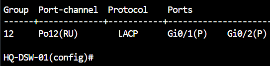
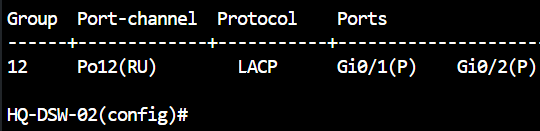
I also wanted to make sure the inter-switch bundle between the distribution switches was solid. A neat design on paper is great, but checking the VLAN, LACP state, and port-channel addresses is what makes it something I can confidently build on. Oh, and on HQ-DSW-01 and HQ-DSW-02, I spun up VLAN 998 purely as a "parking VLAN" for unused ports — gotta keep things secure! 🔒
Need a quick refresher on the addressing math? Review the dual-stack endpoint allocation from Part 2.
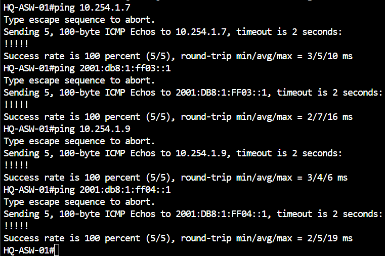
🔀 Dynamic Routing: Firing STP, Hiring OSPF
With the interfaces addressed and happily pinging each other, it was time for the fun part: OSPF! 🎉
I enabled the IPv4 (OSPFv2) and IPv6 (OSPFv3) processes across the routed infrastructure, advertised those loopbacks I mentioned earlier, and let each node learn the rest of the core dynamically.
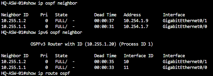
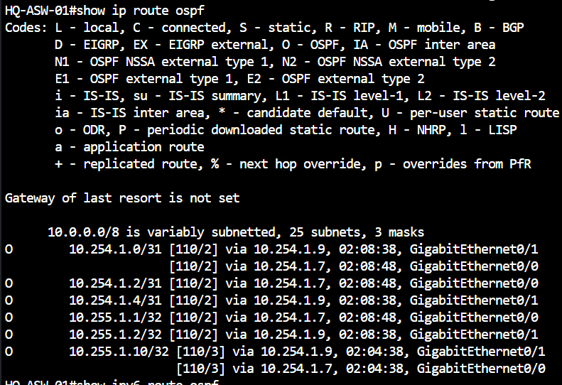
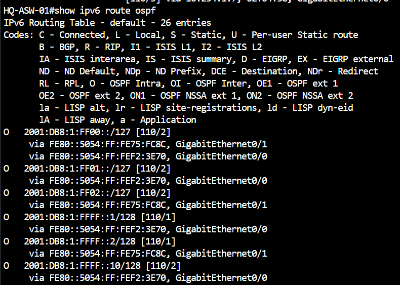
This right here is the ultimate payoff for our Part 2 architecture pivot! 🏆 The routing tables show the learned OSPF routes, meaning we finally get Equal-Cost Multi-Path (ECMP) routing. Instead of having redundant uplinks sitting idle and blocked by Spanning Tree, we get to use all our bandwidth. It gives the lab better performance and a much cleaner failure story.
🧪 Validation: Dual-Stack Pings and ECMP Path Selection
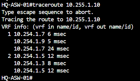
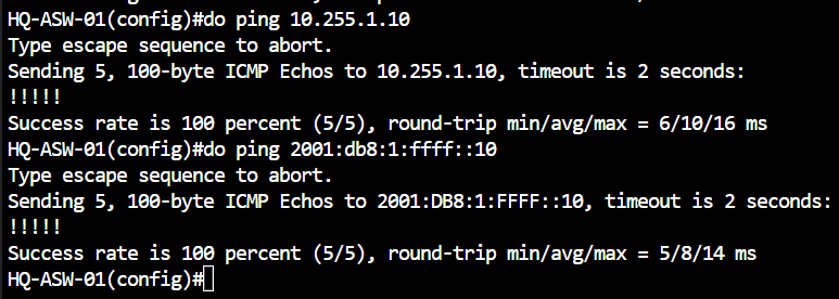
With OSPF established, I needed to prove it actually worked. I ran reachability tests from HQ-ASW-01 all the way to HQ-EDGE-01’s Loopback0. Hitting successful IPv4 and IPv6 pings confirmed that the transit links, learned routes, and return paths were functioning end-to-end.
To make the routing decision visible, I ran a traceroute. It was satisfying to watch the responses alternate through both HQ-DSW-01 and HQ-DSW-02. OSPF successfully installed two equal-cost paths to the edge! The simulation below illustrates this exact behavior.
🛡️ The Failover Test: Proving the Network Survives
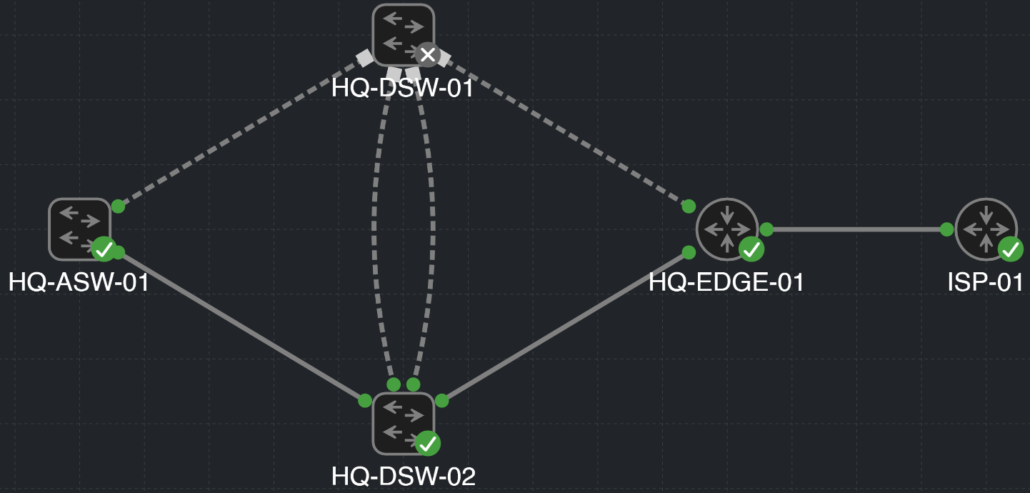
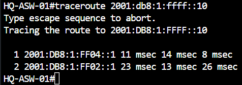
ECMP is awesome, but it’s most valuable when things go wrong. To test our failure path, I deliberately took HQ-DSW-01 completely out of service, just to watch OSPF rip its links out of the topology.
The result? The IPv6 traceroute seamlessly completed through HQ-DSW-02. This is exactly what I wanted: the core automatically shifted to a single path, keeping 100% reachability without me touching a single route. 😎
🔍 Bonus Validation: LACP Resiliency
Finally, if a unidirectional link error breaks one cable in the bundle, what happens?
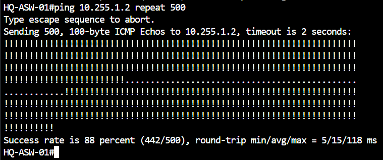
HQ-DSW-01 and HQ-DSW-02 are joined by Port-channel12, a Layer-3 LACP EtherChannel built from GigabitEthernet0/1 and GigabitEthernet0/2. OSPFv2 and OSPFv3 run on that logical port-channel, not on its individual physical members. I used a continuous ping from HQ-ASW-01 to HQ-DSW-02 Loopback0 (10.255.1.2) to observe the result.
Troubleshooting path
Three one-sided tests exposed the same stale member state
I worked from the CML GUI to a manual interface action, keeping the same continuous ping running from HQ-ASW-01 to HQ-DSW-02 Loopback0.
- 01
Stop the link in the CML GUI
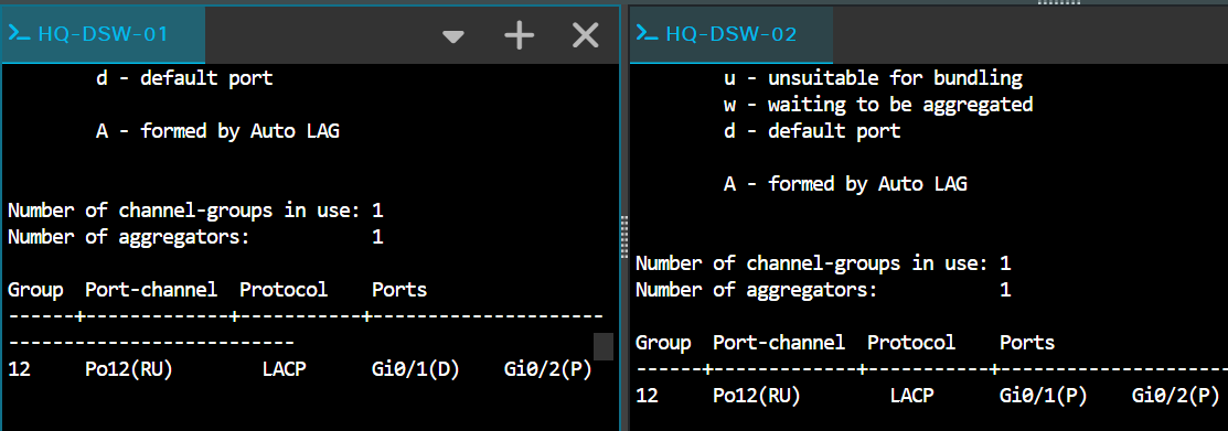
The affected member was stopped, but HQ-DSW-02 still showed it as bundled
(P). The remote switch had not yet removed it from Po12. - 02
Disconnect the link in the CML GUI
The interface status now read as "down", yet the same Po12 member still remained
(P)on HQ-DSW-02. The virtual link looked unavailable while the remote bundle still treated it as usable. - 03
Manually shut the member on HQ-DSW-01 only
I then manually disabled the affected physical member on the HQ-DSW-01 side only. The one-sided state again left HQ-DSW-02 with stale membership, so it could continue sending traffic and OSPF Hellos toward an unavailable path until the OSPF dead timer expired and the adjacency reconverged.
This dropped traffic is just an artifact of a one-sided administrative shutdown in CML/IOSv, not evidence of a broken Layer-3 port-channel config. On real physical hardware (AFAIK), a pulled cable signals "down" on both sides, and the remaining member takes over seamlessly!
Run the controlled two-sided validation
I therefore ran the continuous ping again while manually shutting down the same physical member — GigabitEthernet0/2 — on both distribution switches. Both devices immediately agreed on the active bundle membership, while Port-channel12 remained operational over the remaining member.
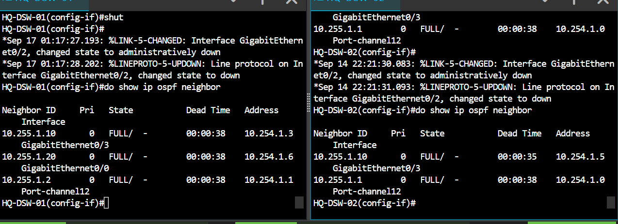
FULL after the controlled test.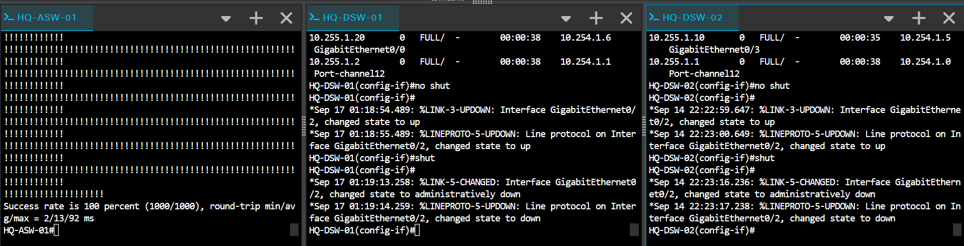
📋 Part 3 summary
Part 3 turned the planned topology into a working dual-stack routed campus core:
- Created the Site 1 VLAN services and dual-stack gateway SVIs on HQ-ASW-01.
- Applied the compact point-to-point addressing approach to the routed infrastructure and checked the inter-switch bundle.
- Formed OSPF adjacencies for IPv4 and IPv6, then verified learned routes and end-to-end reachability.
- Validated ECMP forwarding and the surviving path through HQ-DSW-02 after a simulated distribution-switch failure.
- Confirmed that Port-channel12 retains routing and OSPF reachability when one LACP member is removed in the controlled test.
🔌 What’s next?
The routed core is alive, resilient, and ready for traffic. Up next in Part 4: we start plugging in external endpoints, enterprise services, and our VMware integration to make this lab truly functional. Onward! 🏃♂️💨
📍 The full series roadmap
- ✅ Part 1: CML Environment Setup & Platform Verification
- ✅ Part 2: Five-Node Topology, Dual-Stack Addressing & Routed-Access Foundation
- ✅ Part 3: Dynamic Dual-Stack Routing, ECMP & Path Resiliency (You are here!)
- 🔌 Part 4: External Endpoints, Enterprise Services & VMware Integration
- 🛡️ Part 5: Segmentation, Management & Edge Security
- ☎️ Part 6: Voice, QoS & Unified Communications Integration
- 🤖 Part 7: Network Automation, Programmability & Monitoring
- 🚀 Part 8: CML Personal Expansion — Full Campus, Wireless & Advanced Services
📓 Why I’m documenting the build
This blog is part of my networking portfolio. I want to share my progress, explain what I’m trying to achieve, and be transparent about what goes wrong and how I fix it.
Stay tuned for Part 4!