🏗️ CML Lab Rebuild, Part 2: The Five-Node Foundation (and a Plot Twist!)
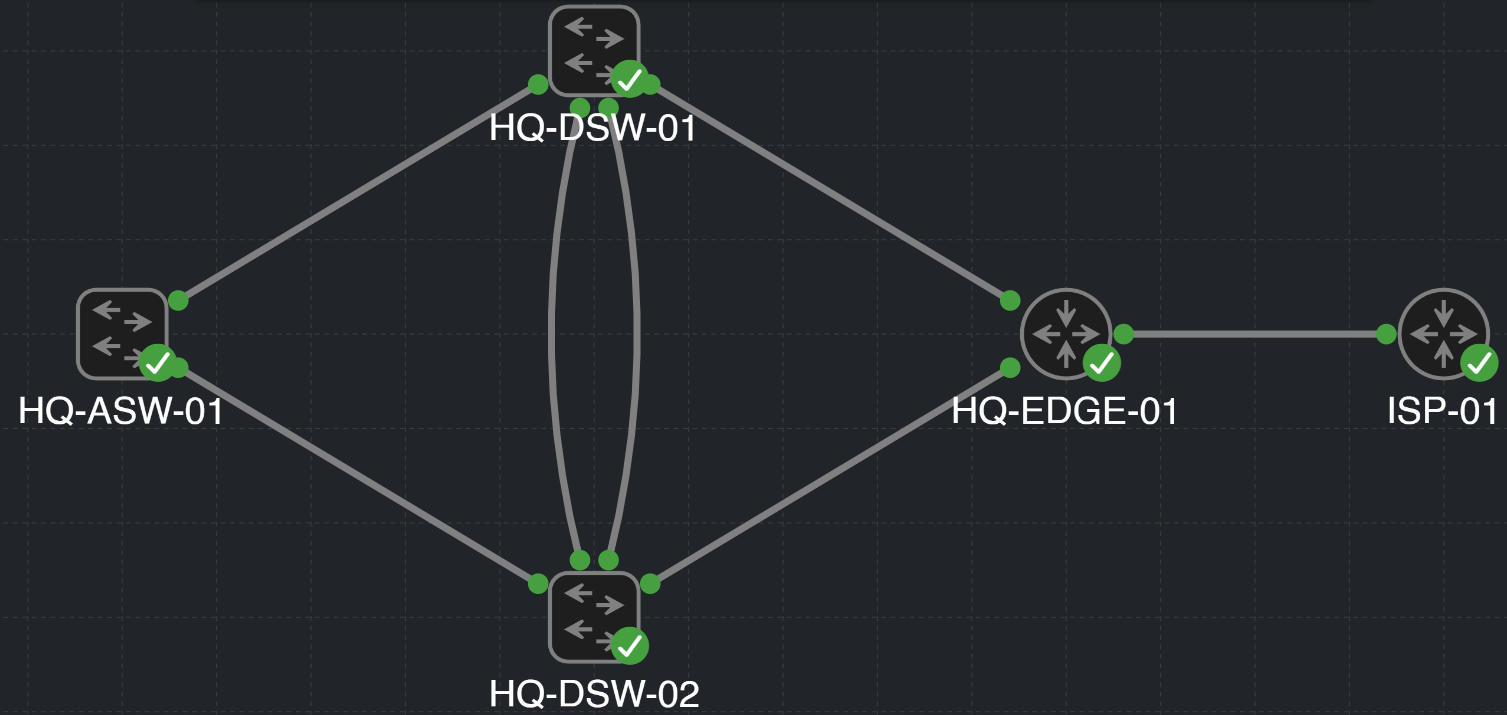
Hello there! 👋 Welcome back to Part 2 of the CML rebuild blog series. As planned, I’ve spun up five nodes in our CML lab, connected the links, and named the devices using a clean format: SITE-DEVICE_TYPE-NUMBER. 🚀
🤔 The Original Plan vs. The Plot Twist
I’ll admit, I was so excited to start labbing that I completely jumped the gun right after adding the nodes! My original plan was to just copy the exact same layout and VLAN scheme from my old CCNA lab and build a classic compact HQ with a collapsed core. That old lab was basically built like a Lego set — completely unplanned and snapped together piece by piece as I progressed through my lectures. I managed to build it, and while it wasn't perfect, hey, everyone starts somewhere! 🤷♂️
It was a very happy-go-lucky approach back then, and while it was great for getting my feet wet, I realized that for this rebuild, I need to actually plan in advance instead of just winging it. I didn't want to just copy-paste my past work; I wanted a genuine learning experience and enjoy the process. So, after taking a step back and doing some research on modern network topologies, I decided to rip up the original plan and pivot to a Routed Campus Design. 🔄
Instead of dealing with Spanning Tree (STP) blocking ports and stretching Layer 2 domains, we are pushing Layer 3 routing all the way down. STP still sticks around for local Layer 2 protection, but it's officially fired from its job of controlling upstream routed paths! 🛑 Instead, OSPF ECMP steps in to handle load balancing and failure resilience, so we can actually utilize all our uplink bandwidth simultaneously instead of having ports sitting idle in a blocking state.
Here is how our five nodes fit into this new, modernized architecture:
- HQ-ASW-01 (Access): Instead of just Layer 2 VLAN trunks, this switch will now participate in routing, eliminating the need for STP to manage redundant uplinks.
- HQ-DSW-01 & 02 (Distribution): These act as our routed core/distribution layer. No more HSRP or complex Layer 2 load balancing — we'll rely on OSPF ECMP!
- HQ-EDGE-01 (Edge Router): The Layer 3 boundary between HQ and the simulated provider.
- ISP-01 (ISP Router): An isolated provider simulation to test a proper external routing boundary.
Even though the logical design shifted halfway through, the physical topology and foundational setups remain exactly the same. 🧱
🚦 Getting Started with VLANs and Subnetting
Now that the routed architecture is officially decided, it was time to tackle the logical side: IP addressing.
Because VLANs and SVIs will now live right on the access switches with purely routed upstream links, my old CCNA addressing scheme wasn't going to cut it. I needed a clean, scalable subnetting plan that would play nicely with our new routed design and give this rebuild a much cleaner path forward. I will admit that what I've come up with is a chaotic combination of lots of research, and plenty of arguing with AI about why X is better than Y 😂 — but I'm honestly still proud of the outcome!
P.S.: Feel free to give me tips on how to improve this plan in the LinkedIn comments or PM me. I know it can be better, and I want to learn from you all! 🙏
📈 A Scalable Private Addressing Plan
Instead of sticking with the tired old 192.168.x.x layout, our rebuilt enterprise topology is graduating to the massive private 10.0.0.0/8 space! This format makes the site and network function instantly readable just by glancing at the address, and it leaves plenty of room for future branches.
Fair warning: we are about to dive deep into the subnetting weeds! 🌿 But by making every single octet actually mean something, this network will effectively document itself. Let's break down the logic:
Addressing structure
A single private range, divided first by site and then by network function.
Site 1 / HQ example
An IT user device at Site 1 uses this address:
10.1.10.25
- Private range
- 10 = private enterprise space
- Site
- 1 = Site 1 / HQ
- Function / subnet
- 10 = IT user network
- Host
- 25 = individual device
Site allocations
- Site 1
- HQ
- 10.1.0.0/16
- Site 2
- Branch
- 10.2.0.0/16
- Site 3
- Future branch
- 10.3.0.0/16
Each site gets its very own shiny /16 block. This makes a site immediately identifiable and gives us a beautifully clean route-summary boundary for when the lab eventually goes multi-site! 🌍
Site 1 VLAN subnet plan
Each function receives a dedicated third-octet range. The first subnet in each range is ready for the initial VLAN.
- IT-USERS
- 10–19
- 10.1.10.0/24
- SERVERS / SERVICES
- 20–29
- 10.1.20.0/24
- HR-USERS
- 30–39
- 10.1.30.0/24
- SALES-USERS
- 40–49
- 10.1.40.0/24
- GUEST-WIFI
- 50–59
- 10.1.50.0/24
- NETWORK-MGMT
- 90–99
- 10.1.99.0/24
- VOICE
- 100–109
- 10.1.100.0/24
How expansion works
The third octet reserves a function range rather than copying the VLAN ID forever. VLAN 30, HR-USERS, starts at 10.1.30.0/24.
When HR needs more capacity, create a new, separate HR user VLAN and subnet:
- First expansion: 10.1.31.0/24
- Further HR subnets: 10.1.32.0/24 through 10.1.39.0/24
Each remains its own VLAN and /24 subnet, so expansion stays predictable instead of cramming multiple networks into one VLAN. 🤝
Now for the fun (and sometimes intimidating) part: IPv6! 🌐 To keep us from going cross-eyed, the IPv6 site and VLAN structure mirrors IPv4 wherever practical. The hexadecimal values at the end of these IPv6 addresses do not mirror IPv4’s decimal host numbers. HQ uses the documentation prefix 2001:db8:1::/48.
IPv6 endpoint pattern
Worked HQ example: an IT user device in VLAN 10.
2001:db8:1:10::25/64
- Documentation prefix
- 2001:db8 = lab-only documentation space
- Site
- 1 = Site 1 / HQ
- VLAN ID
- 10 = IT-USERS network
- Host
- ::25 = individual device
Dual-stack host allocation
Every standard HQ endpoint VLAN follows the same paired convention: an IPv4 /24 and IPv6 /64, with .1 and ::1 reserved for the SVI default gateways.
Standard dual-stack endpoint allocation
VLAN 10 / IT-USERS is the worked example; apply the same host roles to every endpoint VLAN’s own IPv4 subnet and IPv6 prefix.
| Allocation | IPv4 — VLAN 10 | IPv6 — VLAN 10 | Purpose |
|---|---|---|---|
| Network / prefix | 10.1.10.0/24 | 2001:db8:1:10::/64 | Endpoint network boundary |
| Gateway / SVI | 10.1.10.1 | 2001:db8:1:10::1 | Default gateway |
| Fixed / static | 10.1.10.2 – 10.1.10.49 | Selected readable hosts, e.g. ::10, ::20, ::30 | Fixed infrastructure / static hosts |
| Client pool | 10.1.10.50 – 10.1.10.199 | SLAAC and/or DHCPv6 | Dynamic client addressing |
| Future growth | 10.1.10.200 – 10.1.10.239 | Unallocated within /64 | Remaining address space |
| Infrastructure reserve | 10.1.10.240 – 10.1.10.254 | Selected reserved IIDs as required | Reserved static identifiers as required |
| Broadcast | 10.1.10.255 | None — IPv6 uses multicast | IPv4 broadcast boundary |
IPv4 uses defined numerical host ranges for static, DHCP, and reserved addresses. IPv6 does not mirror those decimal ranges. Readable IPv6 host values are used only for selected static infrastructure, while client addresses are assigned dynamically through SLAAC and/or DHCPv6. DHCPv6 does not provide the default gateway; IPv6 clients learn the default router through Router Advertisements.
Final HQ VLAN table
Site 1 / HQ dual-stack VLANs, subnets, and default gateways.
Site 1 / HQ
| VLAN | Name | IPv4 subnet | IPv4 gateway | IPv6 prefix | IPv6 gateway | Purpose |
|---|---|---|---|---|---|---|
| 10 | IT-USERS | 10.1.10.0/24 | 10.1.10.1 | 2001:db8:1:10::/64 | 2001:db8:1:10::1 | IT user endpoints |
| 20 | SERVERS | 10.1.20.0/24 | 10.1.20.1 | 2001:db8:1:20::/64 | 2001:db8:1:20::1 | Server/service endpoints |
| 30 | HR-USERS | 10.1.30.0/24 | 10.1.30.1 | 2001:db8:1:30::/64 | 2001:db8:1:30::1 | HR user endpoints |
| 40 | SALES-USERS | 10.1.40.0/24 | 10.1.40.1 | 2001:db8:1:40::/64 | 2001:db8:1:40::1 | Sales user endpoints |
| 50 | GUEST-WIFI | 10.1.50.0/24 | 10.1.50.1 | 2001:db8:1:50::/64 | 2001:db8:1:50::1 | Guest/untrusted clients |
| 99 | NETWORK-MGMT | 10.1.99.0/24 | 10.1.99.1 | 2001:db8:1:99::/64 | 2001:db8:1:99::1 | Approved management endpoints |
| 100 | VOICE | 10.1.100.0/24 | 10.1.100.1 | 2001:db8:1:100::/64 | 2001:db8:1:100::1 | Voice endpoints |
| 998 | UNUSED-PORTS | None | None | None | None | Parking VLAN for unused ports |
| 999 | NATIVE-VLAN | None | None | None | None | Reserved native VLAN |
Dual-Stack Endpoint
The Final HQ VLAN table above places every IPv4 subnet and gateway beside its IPv6 prefix and gateway. The tables below apply that same paired view to routed links and loopbacks.
Dual-stack routed transit links
Each routed link receives its own paired IPv4 /31 and IPv6 /127 network, keeping the routed-access path easy to trace.
IPv4 transit example
- Site 1 / HQ — distribution Port-Channel12
- 10.254.1.0/31
- Convention
- 10.254.<SITE>.<LINK>/31
- Address breakdown
- 254 = routed transit function, not a VLAN1 = Site 1 / HQ0 = first IPv4 link allocation
IPv6 transit example
- Site 1 / HQ — distribution Port-Channel12
- 2001:db8:1:ff00::/127
- Convention
- 2001:db8:<SITE>:ff<LINK>::/127
- Address breakdown
- ff = routed transit function, not a VLAN1 = Site 1 / HQ00 = first IPv6 link allocation
IPv4 link values advance by two because each /31 uses two addresses. The paired IPv6 networks advance from ff00 through ff04.
| Routed link | IPv4 /31 | IPv6 /127 |
|---|---|---|
| HQ-DSW-01 ↔ HQ-DSW-02 (Port-Channel12) | 10.254.1.0/31 | 2001:db8:1:ff00::/127 |
| HQ-DSW-01 ↔ HQ-EDGE-01 | 10.254.1.2/31 | 2001:db8:1:ff01::/127 |
| HQ-DSW-02 ↔ HQ-EDGE-01 | 10.254.1.4/31 | 2001:db8:1:ff02::/127 |
| HQ-ASW-01 ↔ HQ-DSW-01 | 10.254.1.6/31 | 2001:db8:1:ff03::/127 |
| HQ-ASW-01 ↔ HQ-DSW-02 | 10.254.1.8/31 | 2001:db8:1:ff04::/127 |
🔁 Loopback allocation plan
Think of loopbacks as a device's permanent nametag. 🏷️ By using one consistent format across every site, we give every router and switch a stable, unbreakable identity for SSH and management, completely independent of whatever physical interfaces are bouncing up and down.
Multi-site loopback plan
Reserved IPv4 and IPv6 infrastructure space, structured by site and device ID.
IPv4 loopback example
- Site 1 / HQ — HQ-DSW-01
- 10.255.1.1/32
- Convention
- 10.255.<SITE>.<DEVICE-ID>/32
- Address breakdown
- 255 = loopback function, not a VLAN1 = Site 1 / HQ1 = HQ-DSW-01
IPv6 loopback example
- Site 1 / HQ — HQ-DSW-01
- 2001:db8:1:ffff::1/128
- Convention
- 2001:db8:<SITE>:ffff::<DEVICE-ID>/128
- Address breakdown
- ffff = loopback function, not a VLAN1 = Site 1 / HQ::1 = HQ-DSW-01
Both stacks use the same site and device ID, so a device’s IPv4 and IPv6 loopbacks are easy to match.
Device ID allocations
- 1–9
- Distribution / core
- 10–19
- Edge / security
- 20–99
- Access switches
- 100–199
- Future infrastructure
- 200–239
- Network appliances / services
- 240–254
- Reserved
For the current HQ build:
- HQ-DSW-01
- ID 1
10.255.1.1/322001:db8:1:ffff::1/128- HQ-DSW-02
- ID 2
10.255.1.2/322001:db8:1:ffff::2/128- HQ-EDGE-01
- ID 10
10.255.1.10/322001:db8:1:ffff::10/128- HQ-ASW-01
- ID 20
10.255.1.20/322001:db8:1:ffff::20/128
📝 Addressing Summary
Dual-stack convention at a glance
The same color key follows every address family: prefix, site, network role, then the device or link identifier.
GreenPrivate or documentation prefix
BlueSite identifier
YellowNetwork function or role
PurpleHost, device, or link identifier
- LAN / VLAN networksEndpoint networks
- IPv410.<SITE>.<FUNCTION/SUBNET>.<HOST>
- IPv62001:db8:<SITE>:<VLAN-ID>::<HOST>/64
- ManagementStatic infrastructure access
- IPv410.<SITE>.99.<DEVICE>
- IPv62001:db8:<SITE>:99::<HOST>/64
- LoopbacksStable device identity
- IPv410.255.<SITE>.<DEVICE-ID>/32
- IPv62001:db8:<SITE>:ffff::<DEVICE-ID>/128
- Routed transitsPoint-to-point infrastructure
- IPv410.254.<SITE>.<LINK>/31
- IPv62001:db8:<SITE>:ff<LINK>::/127
Do we need this massive amount of address space for just five tiny CML nodes? Absolutely not. 😂 But we are intentionally designing it this way so the topology can organically grow without forcing us to rip up the floorboards and redesign the entire addressing scheme later!
⚙️ Base Device Configuration
Before applying the shiny new routed design, I needed to establish a consistent device baseline across the topology.
Whether you are building a Layer 2 or Layer 3 network, this baseline is always identical. Before getting to the exciting routing stuff, we have to lock the doors. With the nodes linked up, I applied a consistent starting configuration to establish local administrative access, protect privileged mode, enable SSH, and kill unused HTTP services. 🔒
ip domain name hq.example.test
! Lab baseline only: centralized AAA and management filtering come later
username admin privilege 15 secret <secret>
enable secret <secret>
crypto key generate rsa modulus 2048
ip ssh version 2
no ip http server
no ip http secure-server

! Timeouts are extended for labbing purposes
line console 0
exec-timeout 30 0
 logging synchronous

line vty 0 6
 login local
 transport input ssh
 exec-timeout 10 0
Each device gets its own secure secret values, while the shared baseline keeps our console sessions tidy. 🤫
🗺️ Device and Interface Map
Because the physical links didn't change during my pivot to a routed design, my interface mappings stayed intact. While wiring up each link, I made sure to add interface descriptions — a habit I didn't practice much in my original CCNA lab, but want to build early on here! 💡
Instead of relying on the CML GUI, I used show lldp neighbors to confirm the local interface, neighboring device, and remote port. GUIs are fast, but keeping manual CLI skills sharp is crucial. 🥷
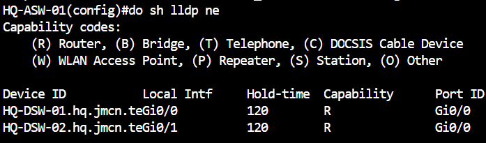
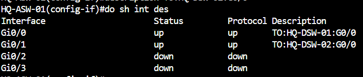
Open the table below to inspect the exact ports and the role of each connection.
Show complete device and interface map
| Connection | Endpoint A | Endpoint B | Interface description and intended role |
|---|---|---|---|
| Access uplink 1 | HQ-ASW-01GigabitEthernet0/0 | HQ-DSW-01GigabitEthernet0/0 | TO:HQ-DSW-01:G0/0Planned routed access-to-distribution uplink. |
| Access uplink 2 | HQ-ASW-01GigabitEthernet0/1 | HQ-DSW-02GigabitEthernet0/0 | TO:HQ-DSW-02:G0/0Planned routed access-to-distribution uplink. |
| Port-Channel12 member 1 | HQ-DSW-01GigabitEthernet0/1 | HQ-DSW-02GigabitEthernet0/1 | First physical member of the planned routed Port-Channel12. |
| Port-Channel12 member 2 | HQ-DSW-01GigabitEthernet0/2 | HQ-DSW-02GigabitEthernet0/2 | Second physical member of the planned routed Port-Channel12. |
| Distribution uplink 1 | HQ-DSW-01GigabitEthernet0/3 | HQ-EDGE-01GigabitEthernet0/0 | Planned routed uplink from the first distribution switch to the HQ edge. |
| Distribution uplink 2 | HQ-DSW-02GigabitEthernet0/3 | HQ-EDGE-01GigabitEthernet0/1 | Planned routed uplink from the second distribution switch to the HQ edge. |
| Provider link | HQ-EDGE-01GigabitEthernet0/2 | ISP-01GigabitEthernet0/0 | External boundary to the isolated ISP simulation; provider addressing is deferred. |
📋 Part 2 Summary
To wrap things up, Part 2 turned our initial five-node CML lab into a documented, scalable foundation:
- Built and mapped the five-node HQ and ISP topology, with a consistent device baseline and interface descriptions.
- Pivoted from the old collapsed-core idea to a routed campus design with Layer 3 uplinks and future OSPF ECMP.
- Defined predictable dual-stack VLAN, endpoint, loopback, and routed-transit allocations that can grow beyond HQ.
Phew! That was intense, and this post is getting a bit long, so I'll continue with the implementation details in Part 3!
🗺️ Next: Part 3 is live!
Click here for Part 3! It puts the Site 1 VLANs, routed uplinks, and OSPF plan into action.
The five-node foundation and address plan are ready. The next stage is to actually apply this shiny new convention to the Site 1 VLANs, SVIs, routed uplinks, and OSPF configuration. Let's get to it in Part 3! 🚀
- HQ access services: Create the Site 1 VLANs and dual-stack SVIs on HQ-ASW-01.
- Routed infrastructure: Apply the IPv4 /31 and IPv6 /127 allocations to the uplinks and configure the infrastructure loopbacks.
- Dynamic routing: Bring up OSPF for IPv4 and IPv6, then validate ECMP and resilient paths through the routed core.
📍 The Full Series Roadmap
Here is the current roadmap for the rest of this CML rebuild series (subject to change if I get distracted by another cool technology 😂):
- ✅ Part 1: CML Environment Setup & Platform Verification
- ✅ Part 2: 5-Node Topology, Dual-Stack Addressing & Routed-Access Foundation
- 🔵 Part 3: Dynamic Dual-Stack Routing, ECMP & Path Resiliency (Now available!)
- 🔌 Part 4: External Endpoints, Enterprise Services & VMware Integration
- 🛡️ Part 5: Segmentation, Management & Edge Security
- ☎️ Part 6: Voice, QoS & Unified Communications Integration
- 🤖 Part 7: Network Automation, Programmability & Monitoring
- 🚀 Part 8: CML Personal Expansion — Full Campus, Wireless & Advanced Services
📓 Why I’m documenting the build
This blog is part of my networking portfolio. I want to share my progress, explain what I’m trying to achieve, and be transparent about what goes wrong and how I fix it.
Part 3 is now available — click here to continue the build.