🚀 CML Lab Rebuild, Part 1: Getting Started with CML-Free
❓Why I’m rebuilding my CCNA lab
While studying for my CCNA, I relied heavily on Cisco Packet Tracer and Jeremy’s IT Lab on Udemy. But as I worked through the lessons, the individual lab exercises started to feel a bit disconnected. I wanted to see the bigger picture and connect the dots! So, instead of treating every topic as a separate exercise, I started building my own topology.😎
That project now covers VLAN segmentation, trunking, inter-VLAN routing, RSTP, EtherChannel, OSPF, HSRP, DHCP, DNS, NAT/PAT, ACLs, IPv4/IPv6, wireless, voice/QoS, and access-layer security controls. It gave me a rock-solid foundation and helped me pass the CCNA — but honestly, I didn't want the fun to end after the exam and I am super excited to continue building and expanding the lab in a more realistic environment!
You can explore the original CCNA Networking Lab here.
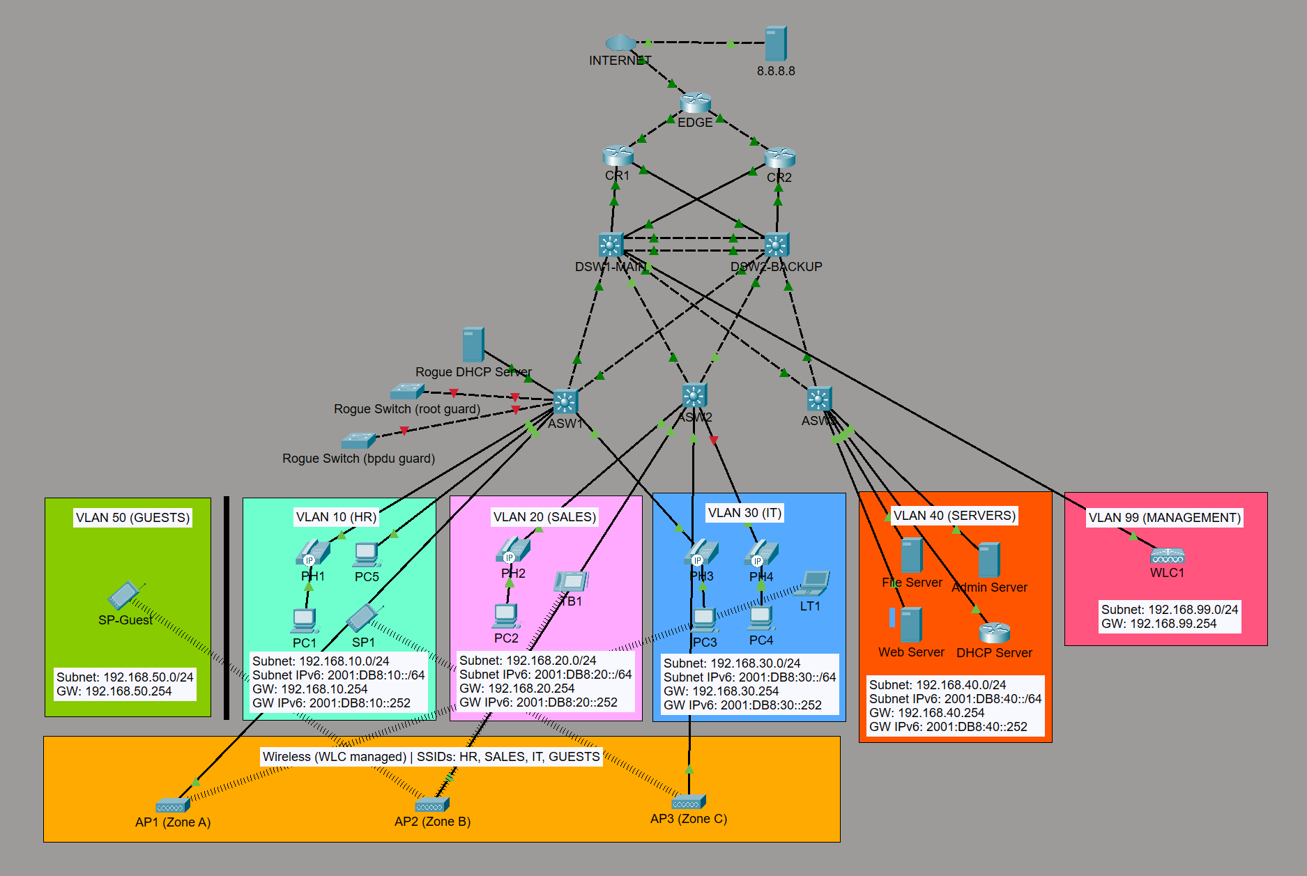
I wanted to keep building in an environment that felt closer to a real-world Cisco workflow: creating nodes, wiring interfaces, opening device consoles, and troubleshooting the platform itself.
I have 3 options to choose from: GNS3, EVE-NG, or CML, and I decided to go with CML because it is the closest to a real Cisco environment where I am familiar with at the moment and I can start with their CML-Free which is a huge advantage. I'll move to other platforms when I need to learn other vendors like Fortinet, Juniper, Palo Alto, etc.
Breaking the Packet Tracer Limits
Packet Tracer is an incredible simulation tool, but it is still a simulator. As my topology grew and I tried to implement beyond what the simulator could handle, I started hitting some limitations and bugs. By migrating to Cisco Modeling Labs (CML), I am upgrading from simulated software to actual Cisco IOS virtual machines.
Here is a breakdown of the Packet Tracer limitations I encountered during my first build and what I am excited to test if the limitations are resolved in CML:
| Feature | Packet Tracer limitation | CML / real IOS capability |
|---|---|---|
| IPv6 first-hop redundancy | IPv6 FHRP is unreliable or buggy, forcing hosts to point directly to SVIs instead of a virtual gateway, as documented in my repository. | Full support for HSRP for IPv6, including standby version 2 and IPv6 link-local virtual IPs. |
| Voice and quality of service | Basic strict-priority queuing is supported, but full Modular QoS CLI support for advanced shaping, policing, and CBWFQ is missing. Congestion and best-effort drops are not simulated realistically, and QoS configuration can fail to persist after a restart. | Deep MQC support across routing platforms, with IOSv-based policy behaviour and more realistic traffic-engineering validation. |
| Layer 2 security and DAI validation | Duplicate IP addressing is prevented, so a true ARP-spoofing attack cannot be simulated to test Dynamic ARP Inspection accurately. | Full Layer 2 attack simulations are possible, such as attaching a Kali Linux VM node. |
| Spanning Tree and EtherChannel | Complex RSTP/LACP interactions and BPDU Guard edge cases can glitch or fail to converge properly in the simulator. | Actual IOSvL2 virtual machines behave like physical Cisco switches. |
| Advanced routing (OSPF) | Basic OSPFv3 capabilities have limited unequal-cost load balancing. | Full OSPFv3 dual-stack support using modern address families. |
| DHCPv6 | Basic SLAAC works, but stateful DHCPv6 and relay agents frequently fail to distribute leases. | Full stateful and stateless DHCPv6 relay and server configurations. |
| Dynamic DNS for end hosts | Dynamic DNS is not supported for end hosts, so their DNS records must be created manually. | A real DNS and DHCP service can provide dynamic client registration and name resolution for a more complete services lab. |
| Wireless LAN and centralized DHCP | Wireless client traffic can appear to originate from the WLC management VLAN instead of the assigned WLAN VLAN. As a documented workaround , the guest WLAN had to use the WLC's internal DHCP. Wireless clients can also attach to random APs rather than choosing an AP based on realistic signal strength. | A centralized DHCP server can provide wireless client leases, keeping wired and wireless addressing in one service instead of relying on WLC internal DHCP. Wireless roaming and RF behaviour should still be validated with an appropriate controller and AP platform. |
| IPv6 security (ACLs) | IPv6 ACL support is limited and relies on basic IPv4-style translation. | Native IPv6 traffic filters and comprehensive extension-header inspection. |
| ACL configuration persistence | Extended ACLs can remain in the saved configuration but stop filtering after the lab is closed and reopened, requiring the VLAN-interface ACL bindings to be applied again. | IOS configuration can be saved and reloaded for repeatable policy testing without relying on a simulator-specific reapplication workaround. |
| Monitoring and logging | SNMP is limited to community-string configurations with SNMPv1/v2, and syslog handling is simplified to the debugging trap level used in this lab. | IOS nodes can be connected to proper monitoring and logging services to practise current SNMP and syslog workflows. |
| Automation and programmability | There is no external API or real script support. | Nodes support Python with Netmiko, Ansible, and RESTCONF for future labs. |
With a clear list of limits to break and an exciting roadmap ahead, I couldn't wait to jump in and start building! Let's dive into how I got the environment setup! 🛠️
🛠️ Setting up CML in VMware Workstation
Setting up CML in VMware Workstation was straightforward. I downloaded the CML-Free OVA file, imported it into VMware, and configured the virtual machine’s CPU, memory, and network settings. After powering on the VM, I can access both cockpit and the CML web interface through a browser.
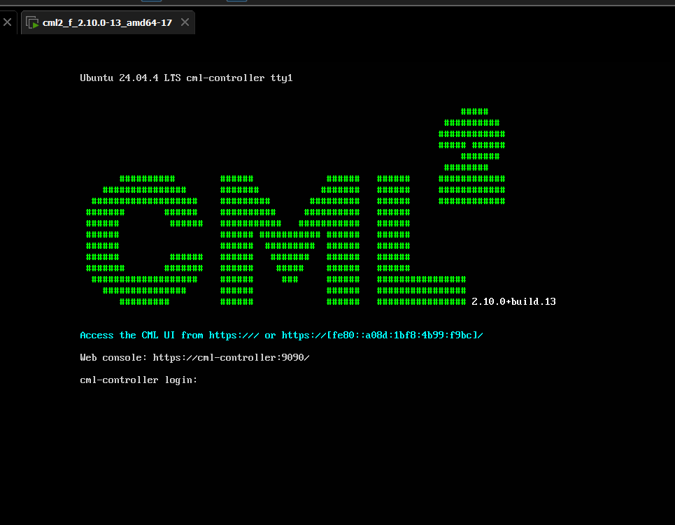
🖥️ Getting into the CML interface
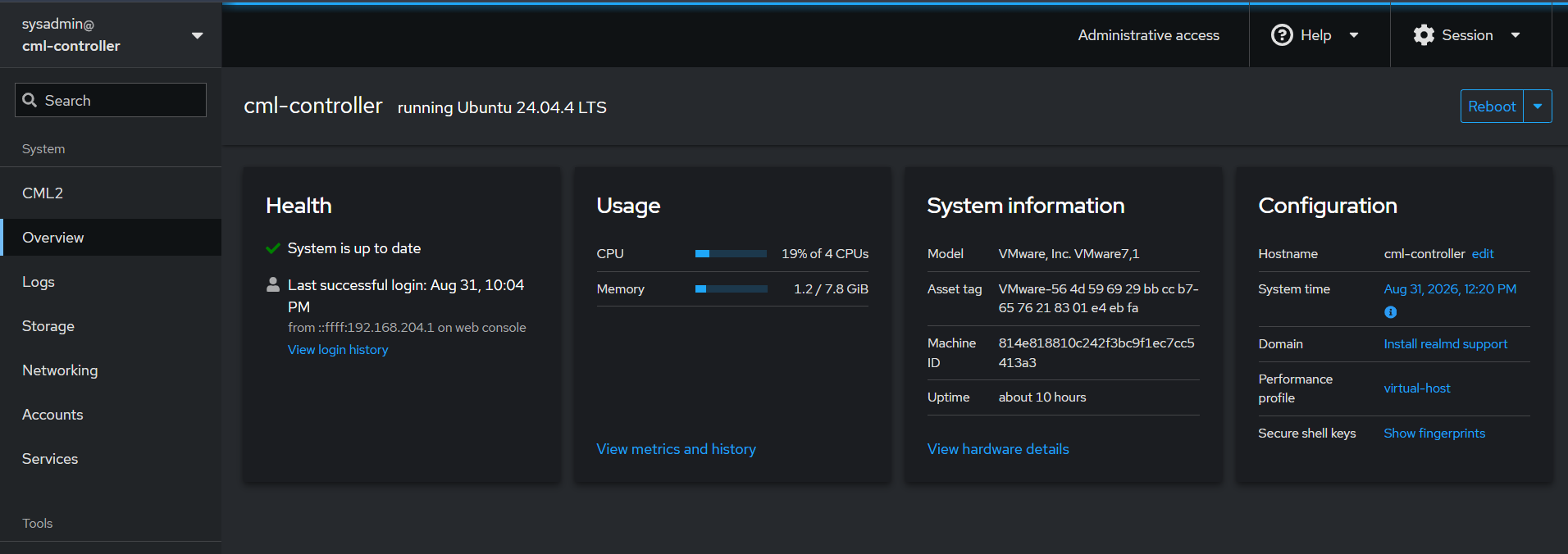
After the initial setup, I jumped into the CML controller in Cockpit. Everything looked great — the Ubuntu virtual machine was running smoothly, and I had a clear view of its CPU, memory usage, uptime, and virtual hardware config.
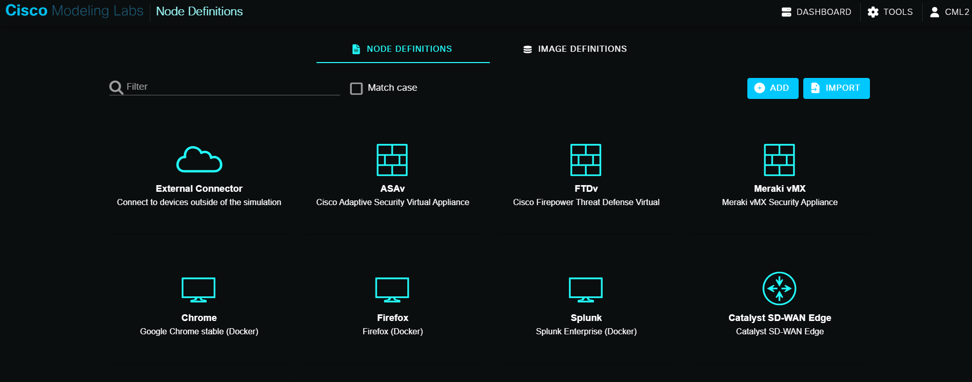
Next, I opened CML's Node Definitions page to explore the available device types. It was awesome getting familiar with the platform's options before diving into the actual build.
⚡ The First Test Drive
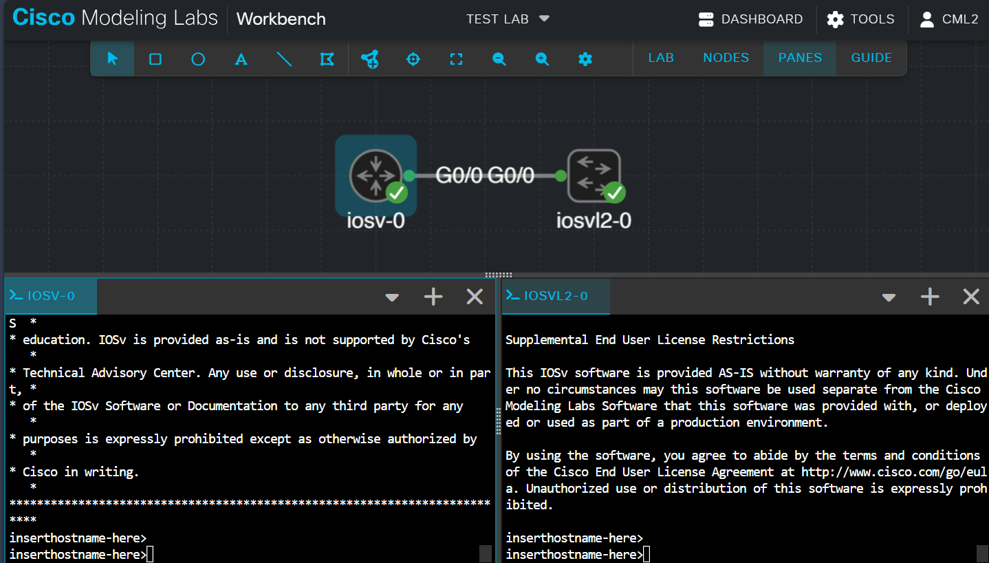
The moment of truth! I created a fresh CML lab, dropped an IOSv router and an IOSvL2 switch onto the canvas, and linked their GigabitEthernet0/0 interfaces. I started both nodes, opened their consoles, and watched the Cisco IOS CLI load up successfully. Seeing that green text confirmed that the node images, lab wiring, and console access were all working perfectly! 🎉
🗺️ What’s Next? (Coming Up in Part 2!)
Now that CML-Free is installed, configured, and verified in VMware, it's time to stop testing and start building!
In Part 2: The Foundation Phase, I’ll be dropping old simulator habits and aligning with clean, realistic design standards for a dual-stack HQ campus. It’s still a lab built for testing and learning, but we are setting it up with best practices in mind! Here is a sneak peek at what’s coming for the new 5-node topology:
- 📐 Clean Design Standards: Moving away from simulator shortcuts by intentionally disabling VTP and DTP, and avoiding internal static routing.
- 🏢 The 5-Node Campus Layout: Deploying clear site-and-role identities across the Access, Distribution, and Edge layers, alongside an ISP simulation node.
- ⚡ Layer 2 Fabric & Addressing: Laying the groundwork with explicit 802.1Q trunks, a Rapid-PVST baseline, and a comprehensive dual-stack IPv4/IPv6 schema. This foundation will set us up perfectly for the HSRP load-balancing in later phases.
📍 The Full Series Roadmap
Here is how the rest of this CML rebuild series will unfold:
- ✅ Part 1: CML Environment Setup & Platform Verification (You are here!)
- 🔜 Part 2: 5-Node Topology Design, Dual-Stack Addressing & Layer-2 Access/Layer-3 Distribution
- 🌐 Part 3: Dynamic Dual-Stack Routing & Gateway Resiliency
- 🔌 Part 4: External Endpoints, Network Services & VirtualBox Integration
- 🛡️ Part 5: Edge Security, Dual-Stack ACLs & IPv4 PAT
- 🤖 Part 6: Network Automation & Programmability
- 🚀 Part 7: CML Personal Expansion: Full Campus, Voice & Wireless
📓 Why I’m documenting the build
This blog is part of my networking portfolio. I want to share my progress, explain what I’m trying to achieve, and be transparent about what goes wrong and how I fix it.
Part 2 is now available — click here for Part 2!